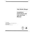
4.8.1 CHECK ITEM Item B1 POWER SUPPLY check Test point Adjustment part Description (1) Receive the black-and-white signal. (color off) (2) Connect the DC voltmeter to the TP-E and TP91(B1) of S1 connector. (3) Confirm that the voltage is DC134.5V±2V. � After reparing the high voltage hold down circuit. This circuit shall be checked to operate correctly. (1) Turn the power switch to on. (2) Refer to the figure, connect the resistor between S1 connector 1-pin and 3-pin. (3) Make sure that the screen picture disappeares. (4) Disconnect the power plug. (5) Remove the resistor. (6) Again connect the power plug. (7) Turn the power switch to on. (8) Make sure that the normal picture is displayed on the screen.
5 4 3 2 1 S1 CONNECTOR
HVT 4
HIGH VOLTAGE Resistor HOLD DOWN (19.0k�, check 1/4W)
HEATER
B1
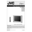
4.8.2 TUNER / IF CIRCUIT Item IF VCO Measuring instrument Remote control unit Test point Adjustment part [9.VCO] CW transf. (T111) [MAIN PWB]
AFC STATUS (Turn to green)
TOO HIGH SYNC: AFC FINE GOOD TOO LOW YES ON 0
Description � It must not adjust without inputting the RF signal. (1) Receive the broadcast. (2) Select 9.VCO from the SERVICE MODE. (3) Set the "AFC" to "OFF" and "FINE" to "0". (4) Confirm that the color change from "TOO HIGH" to "TOO LOW" by CW transf. on MAIN PWB, and check the "SYNC" is "YES". (5) Adjust CW transf. until "GOOD" letters turns green. And then confirm that the "SYNC" is "YES" again. Adjustment can be done in this statement. (6) It return the "AFC" to "ON". (7) Push the [EXIT] key to exit the 9.VCO.
4.8.3 FOCUS Item FOCUS Measuring instrument Signal generator Test point Adjustment part FOCUS VR [In HVT] Description (1) Receive the cross-hatch signal. (2) While watching at the screen, adjust the FOCUS VR to the vertical and horizontal lines will be thinnest and sharpest center horizontal line. (3) Make sure that the picture is in focus even when the screen gets darkened.