Su carrito de compras está vacío
 
English Polski Spanish 
Buscar un manual
 

(p.Ej. AA-V20EG JVC, ZX-7 Sony)
PayPal 1000+ rating Secure, Encrypted Checkout.
 
Usuarios conectados
Actualmente hay 6043 visitantes online.
Productos
Información
Destacado
Inicio >> JVC >> GCQX3U Manual de Servicio
 
 0 artículo(s) en Su carrito 

JVC GCQX3U
Manual de Servicio


¡Twitee acerca de este producto y obtenga $1.00 de crédito en la tienda para uso!
  • Contiene diagramas del circuito
  • Descargable
  • Formato PDF
  • Manual completo
  • Idiomas: English
Precio: $4.99

Descripción del JVC GCQX3U Manual de Servicio

Manual de servicio completo en formato digital (archivo PDF). Los manuales de servicio por lo general contienen diagramas de circuitos, tarjetas de circuitos impresos, consejos para reparación, diagramas de cableado, diagramas de bloque y lista de refacciones. El Manual de Servicio (a veces llamado Manual de Reparación) es usado principalmente por los técnicos.

Si tan solo quiere saber cómo utilizar su televisión, reproductor de vídeo, reproductor de mp3, etc. Quizá lo que necesita es el Manual del Propietario. Después de colocar la orden le enviaremos las instrucciones de descarga a su dirección de e-mail.

The manual is available in languages:

Not yet ready
You must purchase it first

Opiniones de los clientes
No hay comentarios de productos.

TEXT_PDF_SNIPPET
1.3.3 Disassembly method ( II ) <OP Unit>
STEP PART NAME POINT NOTE

1 OP Block ASSEMBLY 2 COVER CCD BASE ASSEMBLY SPACER SET PLATE 3 TILT FRAME RATCH GEAR MAIN PIN 4 RATCH MAGNET NUT ASSEMBLY RATCH PIECE

Remove screws 3 (208) Remove screws 3 (206),2 (207), 1 (236) Remove screws 3(206),2(207). Remove the CCD Board Assy 20(SD1) Remove the SET RING 2 (231) Remove Screws 3 (237),1 (236) Note 1 Note 2 Note 3 Note 4

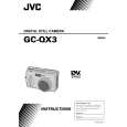
Note 2 Make sure that the torsion spring is in the groove of the latch gear. Note 3 Turn the latch gear clockwise ( ) and position it so that the toothless portion comes to the level that is as high as the main frame.
NOTE2

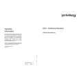
Note 1 Turn and fix the set ring and make sure that the convex marks are identical.

NOTE3

Note 4 Never move the setscrew in the center of the nut assembly!

1

208

203

SET SCREW

208

206
2

202

206
2

234 221 222

Remove screw marks STEP 1 STEP 2 STEP 4 1 2 4

237 225

4

230 224 223

231

204 205

232 226 228 227 229 231

CCD Board Assembly
S2

SD1

207 234 236
4

233 237
4

Fig. 1-3-3

1-6

Quizás también quiera comprar

$4.99

GCQX3U JVC
Manual de Usuario

Manual del propietario completo en formato digital. El manual estará disponible para descarga como …
>
Parse Time: 0.233 - Number of Queries: 101 - Query Time: 0.051