Su carrito de compras está vacío
 
English Polski Spanish 
Buscar un manual
 

(p.Ej. AA-V20EG JVC, ZX-7 Sony)
PayPal 1000+ rating Secure, Encrypted Checkout.
 
Usuarios conectados
Actualmente hay 5689 visitantes y 
3 usuarios online.
Productos
Información
Destacado
Inicio >> JVC >> MXDVB9 Manual de Servicio
 
 0 artículo(s) en Su carrito 

JVC MXDVB9
Manual de Servicio


¡Twitee acerca de este producto y obtenga $1.00 de crédito en la tienda para uso!
  • Contiene diagramas del circuito
  • Descargable
  • Formato PDF
  • Manual completo
  • Idiomas: English
Precio: $4.99

Descripción del JVC MXDVB9 Manual de Servicio

Manual de servicio completo en formato digital (archivo PDF). Los manuales de servicio por lo general contienen diagramas de circuitos, tarjetas de circuitos impresos, consejos para reparación, diagramas de cableado, diagramas de bloque y lista de refacciones. El Manual de Servicio (a veces llamado Manual de Reparación) es usado principalmente por los técnicos.

Si tan solo quiere saber cómo utilizar su televisión, reproductor de vídeo, reproductor de mp3, etc. Quizá lo que necesita es el Manual del Propietario. Después de colocar la orden le enviaremos las instrucciones de descarga a su dirección de e-mail.

The manual is available in languages:

Not yet ready
You must purchase it first

Opiniones de los clientes
No hay comentarios de productos.

TEXT_PDF_SNIPPET
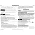
MX-DVB9 Removing the cams R1/R2 assembly and cam gear L (See Fig.23)
Slit washer 1. Remove the slit washer fixing the cams R1 and R2 assembly. 2. By removing the two pawls "S" fixing the cam R1, separate R2 from R1. 3. Remove the slit washer fixing the cam gear L. 4. Pull out the cam gear L from the C.G. base assembly. Cam gear L Slit washer Cam R2

11
Pawl S Pawl S Cam R1

Removing the C.G. base assembly (See Fig.23, 24)
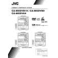
Remove the three screws 11 retaining the C.G. base assembly. [Caution] To re-assemble the cylinder gear, etc. with the cam unit (cam gear and cans R1/R2 assembly), gear unit and drive unit, align the position of the pawl "N" on the drive unit to that of the notch on the cam gear L. Then, make sure that the gear unit is engaged by turning the cam gear L (See Fig. 24).

Cam switch board C.G. base assembly

Fig.23
Cam gear L Cam R1, R2 assembly

Notch

Pawl N Cylinder gear

Gear unit

Drive unit

Gear bracket

Fig.24

1-22

Quizás también quiera comprar

$4.99

MX-DVB9 JVC
Manual de Usuario

Manual del propietario completo en formato digital. El manual estará disponible para descarga como …
>
Parse Time: 0.616 - Number of Queries: 103 - Query Time: 0.268