|
|
|
Usuarios conectados
Actualmente hay 6037 visitantes y
6 usuarios online. |
|
Productos
|
|
Información
|
|
Destacado
|
|
|
 |
|
|
No hay comentarios de productos.
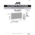
PD-42DXT
DISPLAY INTERFACE PWB H
(x4)
E
(x6)
FILTER SHIELD
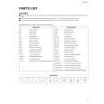
2.4.9 REMOVING THE PDP UNIT (Fig.5) � Remove the REAR COVER. � Remove the TERMINAL COVER. � Remove the CHASSIS BASE (with each PWB affixed on the CHASSIS BASE). (1) Remove the 4 screws [M], and remove the terminal bracket. (2) Disconnect the connectors of the following PWB. NOTE: � Disconnect the connector [CN0PW] from the LINE FILTER PWB. � Disconnect the connectors [CN0AU] and [CN0AT] from the PDP POWER PWB. � Disconnect the connector [CN0AH] and earth wire from the DISPLAY INTERFACE PWB. � It is advisable to take note of the connecting location (connector number) of the removed connectors. Remove the 4 screws [N] and 5 screws [O], and remove the 2 pieces of SUPPORT BRACKET (BOTTOM). Remove the 4 screws [P] and remove the 2 pieces of BACK FRAME (BOTTOM). Remove the 4 screws [Q] and 1 screw [R], and remove the 2 pieces of SUPPORT BRACKET (UPPER). Remove the 2 screws [S] and 1 screw [T], and remove the
PDP POWER PWB I
(x6)
F
(x4)
AUDIO PWB LINE FILTER PWB SYSTEM POWER PWB G
(x4)
(3) (4) (5)
INSULATOR SHEET
(6) Fig.3
2.4.8 REMOVING THE CHASSIS BASE (Fig.4) � Remove the REAR COVER. � � � � � � Remove the TERMINAL COVER. Remove the FILTER SHIELD and LINE FILTER PWB. Remove the AUDIO PWB. Remove the SYSTEM POWER PWB. Remove the DISPLAY INTERFACE PWB. Remove the PDP POWER PWB. (1) Remove the 2 screws [J] and 1 screw [K]. (2) Lift upwards and withdraw the AC inlet in a front direction. (3) Remove the 4 screws [L], and remove the CHASSIS BASE.
panel shield. (7) Remove the 4 screws [U]. (8) Life the PDP upright and remove it with enough care not to impose shock to the PDP. Caution: � Two or more people are required to remove the PDP unit � The gas pouring port is covered with the protection material.In operation, be careful not to damage the gas pouring port. � Do not touch the front side (glass) of the PDP with your fingers.
CHASSIS BASE
L
(x4)
K
J
(x2)
AC INLET COVER
Fig.4
(No.52108)1-11
|
|
|
> |
|