|
|
|
Usuarios conectados
Actualmente hay 5624 visitantes online. |
|
Productos
|
|
Información
|
|
Destacado
|
|
|
 |
|
|
No hay comentarios de productos.
3.2
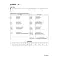
DISASSEMBLY PROCEDURE (RECEIVER UNIT) (Fig. 6) � Remove the DIGITAL INPUT MODULE. � Remove the MI-COM & DIST MODULE PWB and DIST RELAY PWB. (1) Remove the [ CN1001 ] and [ CN1002 ] connector on the MAIN PWB. (2) Remove the [ CN90PW ] [ CN900X ] and [ CN90E1 ] connector on the RECEIVER POWER PWB. (3) Remove the earth wire [ CN90E2 ] from chassis. (4) Remove the 6 screws [ P ]. (5) Take out the RECEIVER POWER PWB. 3.2.7 REMOVING THE FRONT PANEL � Remove the TOP COVER. (1) Remove the 1 screw [ Q ] from front side. (2) Remove the 1 screw [ R ] from top side. (3) Remove the 2 claws [ Y ] from left and right side. (4) Pull out the FRONT PANEL. 3.2.8 REMOVING THE DAMPER � Remove the TOP COVER. � Remove the FRONT PANEL. (1) Remove the 1 screw [ S ] from back side of the FRONT PANEL. (2) Remove the DAMPER. 3.2.9 REMOVING THE FRONT CONTROL PWB � Remove the TOP COVER. � Remove the FRONT PANEL. (1) Remove the card wire from the [ H ] and [ G ] connector. (2) Remove the 4 screws [ T ]. (3) Take out the FRONT CONTROL PWB. 3.2.10 REMOVING THE RECEIVER PWB � Remove the TOP COVER. � Remove the BACK COVER. � Remove the CHASSIS BRACKET. � Remove the DIGITAL INPUT MODULE. � Remove the MI-COM & DIST MODULE PWB and DIST RELAY PWB. (1) Remove the [ CN1005 ] and [ CN1006 ] connector. (2) Pull up the RECEIVER PWB. 3.2.11 REMOVING THE MAIN PWB � Remove the TOP COVER. � Remove the BACK COVER. � Remove the CHASSIS BRACKET. � Remove the DIGITAL INPUT MODULE. � Remove the MI-COM & DIST MODULE PWB and DIST RELAY PWB. � Remove the FRONT PANEL. � Remove the RECEIVER PWB. (1) Remove the 3 screws [ U ] attaching the bracket. (2) Remove the 2 screws [ V ]. (3) Remove the 2 screws [ W ]. (4) Take out the MAIN PWB.
� Make sure that the power cord is pulled out from the AC wall socket. 3.2.1 REMOVING THE TOP COVER (1) Remove the 4 screws [ A ] from both side of the TOP COVER. (2) Remove the 3 screws [ B ] from rear side of the TOP COVER. (3) Pull up the TOP COVER. 3.2.2 REMOVING THE BACK COVER � Remove the TOP COVER. (1) Remove the 2 screws [ C ] attaching the AC connector. (2) Remove the 3 screws [ D ]. (3) Remove the 6 screws [ E ] attaching the each jacks. (4) Remove the 2 screws [ F ] attaching the digital connector. (5) Remove the 2 screws [ G ] attaching the DIGITAL INPUT MODULE. (6) Remove the 2 screws [ H ] attaching the DVI terminal. (7) Remove the 1 nat [ I ] attaching the antenna terminal. (8) Take out the rear cover. 3.2.3 REMOVING THE CHASSIS BRACKET � Remove the TOP COVER. (1) Remove the 2 screws [ J ]. (2) Pull up the CHASSIS BRACKET. 3.2.4 REMOVING THE DIGITAL INPUT MODULE � Remove the TOP COVER. � Remove the BACK COVER. (1) Remove the connector [ AU ], [ SR ], [ DC ], [ Q ] on the DIGITAL INPUT MODULE. (2) Remove the 2 screws [ K ]. (3) Take out the DIGITAL INPUT MODULE. 3.2.5 REMOVING THE MI-COM & DIST MODULE PWB AND DIST RELAY PWB � Remove the TOP COVER. � Remove the BACK COVER. � Remove the DIGITAL INPUT MODULE. (1) Remove the [ CN100A ] connector on the MI-COM & DIST MODULE PWB. (2) Remove the 2 screws [ L ]. (3) Remove the 2 screws [ M ]. (4) Remove the 2 screws [ N ]. (5) Pull up the DIST RELAY PWB from MAIN PWB. (6) Remove the 5 screws [ O ] attaching the MI-COM & DIST MODULE PWB. (7) Take out the MI-COM & DIST MODULE PWB and DIST RELAY PWB from the DIST HOLDER. 3.2.6 REMOVING THE RECEIVER POWER PWB � Remove the TOP COVER. � Remove the BACK COVER.
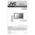
CAUTION AT DISASSEMBLY DIGITAL INPUT MODULE
Prior to disassembly, unplug the power code from the AC outlet without fail. (Turn the power "off".) Short the SB connector [1] pin and [2] pin of the DIGITAL INPUT MODULE. (At the time of assembling) Before the rear panel is inserted into the cabinet, release the short-circuit between the SB connector [1] pin and [2] pin of the DIGITAL INPUT MODULE. After releasing the short-circuit between the SB connectors, do not turn the power on until the rear panel is inserted into the cabinet. Negligence in carrying out the above steps may cause the inactivation of the TV.
1 3 5
2 4 SB connector 6
BACK COVER
1-16 (No.YA029)
|
|
|
> |
|