Su carrito de compras está vacío
 
English Polski Spanish 
Buscar un manual
 

(p.Ej. AA-V20EG JVC, ZX-7 Sony)
PayPal 1000+ rating Secure, Encrypted Checkout.
 
Usuarios conectados
Actualmente hay 5885 visitantes online.
Productos
Información
Destacado
Inicio >> JVC >> RVDP200BK Manual de Servicio
 
 0 artículo(s) en Su carrito 

JVC RVDP200BK
Manual de Servicio


¡Twitee acerca de este producto y obtenga $1.00 de crédito en la tienda para uso!
  • Contiene diagramas del circuito
  • Descargable
  • Formato PDF
  • Manual completo
  • Idiomas: English
Precio: $4.99

Descripción del JVC RVDP200BK Manual de Servicio

Manual de servicio completo en formato digital (archivo PDF). Los manuales de servicio por lo general contienen diagramas de circuitos, tarjetas de circuitos impresos, consejos para reparación, diagramas de cableado, diagramas de bloque y lista de refacciones. El Manual de Servicio (a veces llamado Manual de Reparación) es usado principalmente por los técnicos.

Si tan solo quiere saber cómo utilizar su televisión, reproductor de vídeo, reproductor de mp3, etc. Quizá lo que necesita es el Manual del Propietario. Después de colocar la orden le enviaremos las instrucciones de descarga a su dirección de e-mail.

The manual is available in languages:

Not yet ready
You must purchase it first

Opiniones de los clientes
No hay comentarios de productos.

TEXT_PDF_SNIPPET
RV-DP200BK

<CD Unit >
Prior to performing the following procedure, remove the front cabinet, the rear cabinet and the CD unit.
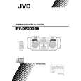
CN419 CN418 Main Switch board CN410 CN417

Removing the main switch board and illumination boad. (See Fig.22)
1. Disconnect the card wire from connector CN411 and CN412, and the harness from CN401,CN419 and CN410 of the main switch board on the underside of the CD unit. 2. Remove the four screws R attaching the main switch board and illumination board.

R
CN413

R
CN411 CN412

CN415

R
Illumination board

R
CD unit Fig.22
CN401

Removing the micon board

(See Fig.23)

Prior to performing the following procedure, remove the main switch board. CAUTION: Prior to disconnecting the card wire from connector CN601 on the micom board, solder the short-circuit land on the pickup unit. Disconnecting the card wire extending from the pickup unit may cause damage to the pickup unit. When reassembling, unsolder the short-circuit land on the pickup unit after connecting the card wire to connector CN601. Fig.25 shows more detail about the short-circuit land.

CN602

S
CN601

S
CN412

(Disconnect after soldering the short-circuit land.)

d
CN911 CN916 CN422

S

S

Micom board

CN912

Fig.23

1. Disconnect the card wires from connector CN601 and CN911 on the micon board. 2. Remove the spacer fixing the harnesses marked d. 3. Remove the four screws S attaching the micon board. 4. Disconnect the harness from connector CN912 and CN602 on under side of the micon board respectively.

1-11

Quizás también quiera comprar

$4.99

RVDP200BK JVC
Manual de Usuario

Manual del propietario completo en formato digital. El manual estará disponible para descarga como …
>
Parse Time: 0.165 - Number of Queries: 101 - Query Time: 0.035