|
|
|
Usuarios conectados
Actualmente hay 6043 visitantes online. |
|
Productos
|
|
Información
|
|
Destacado
|
|
|
 |
|
|
No hay comentarios de productos.
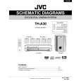
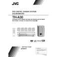
TH-A30
Removing the DSP board
(See Fig.9)
Prior to performing the following procedure, remove the top cover, front panel assembly, DVD mechanism assembly and jack board. 1. Remove the harness band fixing the harness. 2. Disconnect the harness from the connector J9 and J10 on the DSP board. 3. Disconnect the card wire from the connector J1 and J3 on the DSP board. 4. Remove the one screw L attaching the DSP board. 5. Remove the screw M1 and remove the earth wire. 6. Remove the one screw I attaching the DSP board to the rear panel (see fig.7). 7. Pull up the DSP board from the front side upwards disconnecting the connector J2, J5, J6 and J7.
Harness band DSP board
J3 J1
J10 J9
L
J6
J5 J7
J2
(fixing the earth wire)
M1
Fig.9
Main board
M2
Removing the main board
(See Fig.10)
Prior to performing the following procedure, remove the top cover, front panel assembly, power cord, DVD mechanism assembly, jack board and DSP board. ACW2 1. Disconnect the card wire from the connector CW8 on the main board. 2. Disconnect the harness from the connector ACW2, ACW3, ACW4 and ACW5 on the main board. 3. Remove the five screws J attaching the speaker terminals and jack to the rear panel (see fig.7). 4. Remove the nine screws M2 attaching the main board. 5. When the rear panel is not removed, pull up the main board from front side.
CW8
(Rear panel side)
Heat sink1
M2
Heat sink2 ACW3
M2
M2
Heat sink3
Fig.10
Solder part 1 (Each power transistor is fixed)
ACW5 ACW4
Main board (Reverse side )
Removing the power transistor & power IC (See Fig.10 to 12)
Prior to performing the following procedure, remove the top cover, front panel assembly, DVD mechanism assembly, jack board, DSP board and main board. 1. After removing the solder part 1 soldered to the main board, remove each screw and remove the heat sink from the power transistor. 2. After removing the solder part 2 soldered to the main board, remove each screw and remove the heat sink from the power IC.
Solder part 3 (Power IC is fixed) Solder part 2 (Power IC is fixed)
Fig.11
1-7
(Front panel side)
|
|
|
> |
|