Su carrito de compras está vacío
 
English Polski Spanish 
Buscar un manual
 

(p.Ej. AA-V20EG JVC, ZX-7 Sony)
PayPal 1000+ rating Secure, Encrypted Checkout.
 
Usuarios conectados
Actualmente hay 5933 visitantes online.
Productos
Información
Destacado
Inicio >> JVC >> XM-PX33-WT/BU Manual de Servicio
 
 0 artículo(s) en Su carrito 

JVC XM-PX33-WT/BU
Manual de Servicio


¡Twitee acerca de este producto y obtenga $1.00 de crédito en la tienda para uso!
  • Contiene diagramas del circuito
  • Descargable
  • Formato PDF
  • Manual completo
  • Idiomas: English
Precio: $4.99

Descripción del JVC XM-PX33-WT/BU Manual de Servicio

Manual de servicio completo en formato digital (archivo PDF). Los manuales de servicio por lo general contienen diagramas de circuitos, tarjetas de circuitos impresos, consejos para reparación, diagramas de cableado, diagramas de bloque y lista de refacciones. El Manual de Servicio (a veces llamado Manual de Reparación) es usado principalmente por los técnicos.

Si tan solo quiere saber cómo utilizar su televisión, reproductor de vídeo, reproductor de mp3, etc. Quizá lo que necesita es el Manual del Propietario. Después de colocar la orden le enviaremos las instrucciones de descarga a su dirección de e-mail.

The manual is available in languages:

Not yet ready
You must purchase it first

Opiniones de los clientes
No hay comentarios de productos.

TEXT_PDF_SNIPPET
XM-PX33BU/XM-PX33WT

<Removal of the MD mechanism>
Removing the spindle motor (See Fig.9)
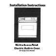
1. Unsolder the part e of the flexible wire extending from the underside of the chassis assembly to the spindle motor. At this time, do not spill flux on the gear and others. 2. Remove the three screws G attaching the spindle motor and detach it from the chassis assembly.

Slit washer Worm gear

H

Shaft holder e

G

chassis assembly

Spindle motor f g Pickup unit

Removing the pickup unit (See Fig.9)
1. Remove the slit washer and the worm gear from the underside of the chassis assembly. 2. Remove the screw H then detach the shaft. attaching the shaft holder,

Lead screw

Fig.9

3. Pull out the part f and g in the directions of the arrows to remove the pickup unit and the lead screw.
Lead screw

I
Lead spring

Removing the pickup (See Fig.10 and 11)
1. Remove the screw I attaching the lead spring, then detach the lead spring. 2. Pull out the shaft from the pickup. ATTENTION: When handling the pickup unit, touch the parts marked in Fig.11 only. Fig.10

Pickup

Touch the parts only.

Fig.11

1-7

Quizás también quiera comprar

$4.99

SX-K700 TECHNICS
Manual de Usuario

Manual del propietario completo en formato digital. El manual estará disponible para descarga como …

$4.99

CJ-V51 PIONEER
Manual de Servicio

Manual de servicio completo en formato digital (archivo PDF). Los manuales de servicio por lo genera…

$4.99

GRAND PRIX ELECTRONIC 754 BECKER
Manual de Servicio

Manual de servicio completo en formato digital (archivo PDF). Los manuales de servicio por lo genera…

$4.99

SX-PR602 TECHNICS
Manual de Servicio

Manual de servicio completo en formato digital (archivo PDF). Los manuales de servicio por lo genera…

$4.99

EV-S1000E SONY
Manual de Usuario

Manual del propietario completo en formato digital. El manual estará disponible para descarga como …

$4.99

GRAND PRIX ELECTRONIC 780 BECKER
Manual de Servicio

Manual de servicio completo en formato digital (archivo PDF). Los manuales de servicio por lo genera…

$4.99

AG7330 PANASONIC
Manual de Servicio

Manual de servicio completo en formato digital (archivo PDF). Los manuales de servicio por lo genera…

$4.99

EVO-9850 VOLUME 1 SONY
Manual de Servicio

Manual de servicio completo en formato digital (archivo PDF). Los manuales de servicio por lo genera…
>
Parse Time: 0.377 - Number of Queries: 130 - Query Time: 0.159