Su carrito de compras está vacío
 
English Polski Spanish 
Buscar un manual
 

(p.Ej. AA-V20EG JVC, ZX-7 Sony)
PayPal 1000+ rating Secure, Encrypted Checkout.
 
Usuarios conectados
Actualmente hay 5869 visitantes online.
Productos
Información
Destacado
Inicio >> JVC >> XVD9000 Manual de Servicio
 
 0 artículo(s) en Su carrito 

JVC XVD9000
Manual de Servicio


¡Twitee acerca de este producto y obtenga $1.00 de crédito en la tienda para uso!
  • Contiene diagramas del circuito
  • Descargable
  • Formato PDF
  • Manual completo
  • Idiomas: English
Precio: $4.99

Descripción del JVC XVD9000 Manual de Servicio

Manual de servicio completo en formato digital (archivo PDF). Los manuales de servicio por lo general contienen diagramas de circuitos, tarjetas de circuitos impresos, consejos para reparación, diagramas de cableado, diagramas de bloque y lista de refacciones. El Manual de Servicio (a veces llamado Manual de Reparación) es usado principalmente por los técnicos.

Si tan solo quiere saber cómo utilizar su televisión, reproductor de vídeo, reproductor de mp3, etc. Quizá lo que necesita es el Manual del Propietario. Después de colocar la orden le enviaremos las instrucciones de descarga a su dirección de e-mail.

The manual is available in languages:

Not yet ready
You must purchase it first

Opiniones de los clientes
No hay comentarios de productos.

TEXT_PDF_SNIPPET
XV-D9000

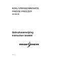
Removing the audio(rear L/R) board (See Fig.12~13)
*Prior to performing the following procedure, remove the top panel and rear cover. 1.Remove the three screws L attaching the audio(rear L/R) board. 2.Remove the four screws M attaching the audio(rear L/R) board from back of the body. 3.Disconnect the card wire from CN761 and connector from CN751 on the audio(rear L/R) board. 4.Disconnect the connector from CN697 on the audio power board. CN751 CN761 CN697 Audio-analog (rear L/R)board Fig.12 M

L

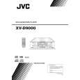
Removing the audio(front L/R) board (See Fig.14)
*Prior to performing the following procedure, remove the top panel and rear cover. 1.Remove the audio(rear L/R) board(upper step). 2.Remove the two screws N of the pillar which supports audio(rear L/R) board(upper step). 3.Remove the two screws O attaching the audio(front L/R)board(lower step). 4.Disconnect the connector from CN721 and CN722 on the audio signal(front) output terminal. 5.Disconnect the connector from CN695 and CN696 on the DVD audio power board. 6.Disconnect the connector from CN741 on the signal processing board. Signal processing board CN741

Fig.13 Audio-analog (front L/R)board

N O

CN696 CN722 CN721 CN695 Fig.14

1-10

Quizás también quiera comprar

$4.99

XVD9000 JVC
Manual de Usuario

Manual del propietario completo en formato digital. El manual estará disponible para descarga como …
>
Parse Time: 0.182 - Number of Queries: 101 - Query Time: 0.047